Within the Converged Access platform there are a few features which can benefit from the use of multicast traffic flows. In this post I discuss which these features are and how they need to be configured.
1. Generic multicast configuration
First of all some generic multicast configuration needs to be in place on which the other features rely. For this post I use two 3650 switches (CAT1 and CAT2) which are directly connected to each other. The wireless management interface is VLAN 601 for both switches. IP multicast routing will be enabled globally and for both switches one switch will be statically configured as as RP for PIM.
CAT1(config)#ip multicast-routing

CAT1(config)#ip pim rp-address 10.60.1.254

CAT1(config)#int vlan 601

CAT1(config-if)#ip pim sparse-mode
2. “Multicast-multicast” mode for client multicast traffic
To distribute the client multicast (and broadcast) traffic as efficient as possible between the switches and the access-points, we can use “multicast-multicast” mode. In this configuration the client traffic will be send to the access-points with multicast as well.
CAT1(config)#wireless multicast

CAT1(config)#ap capwap multicast 239.44.44.44
Once enabled you can see that a dedicated Capwap interface is being created, which is “Ca1” in this scenario with the SVI of the CAT1 switch as source IPv4 address.
CAT1#show capwap summary

Name   APName                           Type PhyPortIf Mode      McastIf

------ -------------------------------- ---- --------- --------- -------

Ca1    -                                mcas -         unicast   -

Ca2    3502I                            data Gi1/0/2   multicast Ca1

Ca3    2602E                            data Gi1/0/3   multicast Ca1
Name SrcIP SrcPort DestIP DstPort DtlsEn MTU Xact
------ --------------- ------- --------------- ------- ------ ----- ----
Ca1 10.60.1.254 5247 239.44.44.44 5247 No 1449 1
On layer 2 level we see that IGMP snooping is active for the two ports on which the access-points are connected.
CAT1#show ip igmp snooping groups

Vlan      Group                 Type        Version     Port List

------------------------------------------------------------------------

601       239.44.44.44          igmp        v2          Gi1/0/2, Gi1/0/3
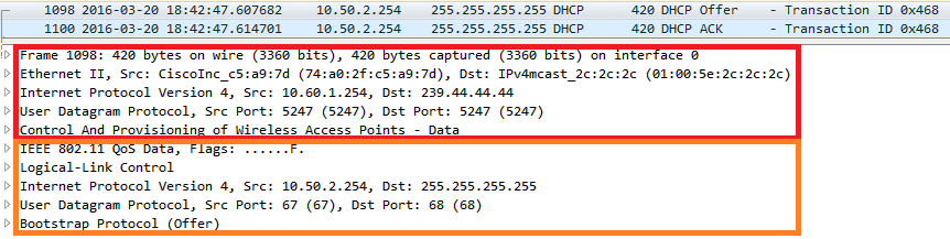
So how does this looks like on the wire? In the red box in the picture below you see the actual multicast packet, the orange box is the encapsulated client (broadcast) traffic.
3. Multicast traffic within Switch Peer Group
Converged Access works with Mobility Controller (MC) and Mobility Agent (MA) roles in certain Switch Peer Groups (SPG). Those SPG should be designed around areas where extensive roaming is going to happen like one building or floors. Within a SPG you only have one MC but you can have multiple MAs which all need to communicate with each other. Some communication can be done with multicast as well which can be more efficient if you have a few MAs within the SPG. Below the configuration for the MC (CAT1 – 10.60.1.254) and MA (CAT2 – 10.60.1.250).
CAT1(config)#wireless mobility co peer-group MA

CAT1(config)#wireless mobility co peer-group MA member ip 10.60.1.250

CAT1(config)#wireless mobility co peer-group MA multicast ip 239.33.33.33

CAT2(config)#wireless mobility co ip 10.60.1.254
The multicast address configuration is being pushed by the MC to the MA:
CAT2#*Mar 19 21:33:30.843: *%MM-6-SOCK_SET_ADDRESS_OPTION: 1 wcm: Setting membership for interface IP 10.60.1.250 and multicast group 239.33.33.33 on the mobility sockets.
CAT2#show wireless mobility summary
Mobility Agent Summary:
Mobility Role : Mobility Agent
Mobility Protocol Port : 16666
Mobility Switch Peer Group Name : MA
Multicast IP Address : 239.33.33.33
So how does this looks like on the wire? Below you can see the messages being send by the MA when one clients roams between APs connected on CAT1 and CAT2.

4. Multicast traffic between MCs (in different mobility domains)
In this scenario both CAT1 (10.60.1.254) and CAT2 (10.60.1.250) are MCs and belong to different mobility domains. Again the use multicast to communicate with each other. Note: from my own testing I have seen that it is not required to use different multicast address for this.
CAT1(config)#wireless mobility controller

CAT1(config)#wireless mobility group name MC1

CAT1(config)#wireless mobility multicast ip 239.33.33.35

CAT1(config)#wireless mobility group member ip 10.60.1.250 group MC2

CAT1(config)#wireless mobility group multicast-address MC2 ip 239.33.33.36

CAT2(config)#wireless mobility controller

CAT2(config)#wireless mobility group name MC2

CAT2(config)#wireless mobility multicast ip 239.33.33.36

CAT2(config)#wireless mobility group member ip 10.60.1.254 group MC1

CAT2(config)#wireless mobility group multicast-address MC1 ip 239.33.33.35