All posts by Freerk

Cisco WLC rate limiting

This time a short post about rate limiting on an Cisco AirOS WLC. Under the QoS tab of the SSID configuration you can find two categories of rate-limiting settings; per user and per SSID. For both categories you can specific UDP and TCP rates, however those settings are being applied on the specific radios of the access-point and not on the controller! Below two examples to illustrate what this means.

Two clients on the same AP and on the same radio
3Mbit policy:
AP#show int gigabitEthernet 0 | i input rate
30 second input rate 3359000 bits/sec, 300 packets/sec

6Mbit policy:
AP#show int gigabitEthernet 0 | i input rate
30 second input rate 6346000 bits/sec, 581 packets/sec

Two clients on the same AP and on different radios
3Mbit policy:
AP#show int gigabitEthernet 0 | i input rate
30 second input rate 6391000 bits/sec, 576 packets/sec

6Mbit policy:
AP#show int gigabitEthernet 0 | i input rate
30 second input rate 12325000 bits/sec, 1108 packets/sec

So if you expect an “global maximum per SSID” you will find that the configured value will not work with multiple access-points and clients. You have to really dive deep in the documentation from Cisco to find this. I guess Cisco had some complains about this as well because since software version 8.0 the related footnote (number 16) for this configuration item got changed. The added “Override Bandwidth Contracts parameters are specific to per Radio of AP.” Yeah, about time…

A better location for your traffic engineering is in my opinion somewhere on the next-hop router or firewall, the WLC is really not the device to do this. The (re)marking of traffic is fine, enforcing policies is another story.
Simple IOS-XE mDNS configuration for AppleTV

This post is a small “tech note” about how to configure mDNS in IOS-XE to support AppleTV. In this example the AppleTV is located in VLAN 101 and the client in VLAN 107.

First enable mDNS and configure the switch to query for AirPlay and AirTunes services (AirTunes is necessary for AppleTV to work as well).
service-list mdns-sd MDNS-QUERY query
service-type _airplay._tcp.local
service-type _raop._tcp.local
service-routing mdns-sd
service-policy-query MDNS-QUERY 60

Configure service lists so that only AirPlay and AirTunes announcements will be accepted on the VLAN101 interfaces.
service-list mdns-sd MDNS-VLAN101-IN permit 10
match message-type announcement
match service-type _airplay._tcp.local
service-list mdns-sd MDNS-VLAN101-IN permit 20
match message-type announcement
match service-type _raop._tcp.local
service-list mdns-sd MDNS-VLAN101-IN deny 30

From the client side we only process AirPlay and AirTunes queries.
service-list mdns-sd MDNS-VLAN107-IN permit 10
match message-type query
match service-type _airplay._tcp.local
service-list mdns-sd MDNS-VLAN107-IN permit 20
match message-type query
match service-type _raop._tcp.local
service-list mdns-sd MDNS-VLAN107-IN deny 30

Because we apply the filtering on the inbound side, outbound filtering is not required.
service-list mdns-sd MDNS-VLAN101-OUT permit 10
service-list mdns-sd MDNS-VLAN107-OUT permit 10

Apply the service lists on the interfaces.
interface Vlan101
service-routing mdns-sd
service-policy MDNS-VLAN101-IN IN
service-policy MDNS-VLAN101-OUT OUT
interface Vlan107
service-routing mdns-sd
service-policy MDNS-VLAN107-IN IN
service-policy MDNS-VLAN107-OUT OUT

Validate that records are visible.
CAT3650# show mdns cache
_airplay._tcp.local PTR IN 4500/4496 0 Vl101 a431.3514.b907
_raop._tcp.local PTR IN 4500/4496 1 Vl101 a431.3514.b907
AppleTV._airplay._tcp.local SRV IN 4500/4496 1 Vl101 a431.3514.b907

Cisco IOS / IOS-XE and DHCPv6 option 52 (RFC 5417)

First post in the year 2016! Will this be “the” year for IPv6? Who knows, but at least this post will be about IPv6 which is a start right? 🙂

If you have 3500’s or newer type of access-points with AirOS 8.x software on your WLC’s you can use native IPv6 as protocol for the CAPWAP traffic. The way that AP’s initially try to discover WLC’s with IPv6 is not that different comparing with IPv4:
1. DHCPv6 Option 52
2. Multicast Discovery (L2)
3. DNS
4. Static AP priming

More than once I have used Cisco’s native DHCP server in IOS/IOS-XE to supply AP’s with information about the WLC’s (with DHCPv4 this is option 43). I wanted the same with IPv6 so I configured the following:

ipv6 dhcp pool IPV6-DHCP-VLAN106
address prefix 2002:1234:CC1E:106::/64
vendor-specific 52
suboption 1 address 2002:1234:CC1E:105::11

On the AP side something strange was happening. Instead of showing “CAPWAP Access controller: <IPv6 address> ” it showed the following output:

AP#show ipv6 dhcp interface
Vendor-specific Information options:
Enterprise-ID: 52

After more than one hour of fiddling with the configuration and troubleshooting I reached out to TAC. It turns out that the current DHCPv6 implementation on IOS and IOS-XE simply don’t support DHCPv6 option 52 (RFC 5417). Because of this TAC filled the feature enhancement CSCux73480. More information about DHCPv6 option 52 configuration for other DHCPv6 servers can be found in this document.

Cisco’s converged access and (in)directly connected access-points

In every document you can find about Cisco’s converged access you will read that with 3650 and 3850 switches access-points need to be directly connected. I understand the reasons why Cisco requires that, but the nerd in me wanted to know how that it works and if the switch can be tricked in the process. So what happens if you connect an access-point on another layer 2 switch and build a dot1Q trunk between that switch and the 3650/3850?

Nov 18 00:58:18.893: %CAPWAP-3-AP_PORT_CFG: AP connected port Gi1/0/24 is not an access port.

Busted! But what happens when we make it an access port? Great success! Sadly this only works for just the first access-point. So to summarize the requirements if you really need/want to do this:
1. The access-point needs to be in the same VLAN as the wireless management interface of the 3650/3850 switch
2. The interface where the access-point is being located on/after needs to be in access mode
3. Only one access-point per interface.

Note: I tested this on an 3650 with IOS-XE 03.06.00E, but I do not believe that this is something what will change in newer software versions.

Downstream QoS fails with Cisco Flexconnect local authentication enabled

For a customer we are currently deploying a new wireless network infrastructure with voice over wireless (VoWLAN) as primary use-case. In this deployment we use Flex-connect with 2700 / 3700 AP’s, a virtual WLC and Cisco’s own 7925G wireless phones.

In the testing phase we discovered that the Cisco 7925G phones showed that while making a voice call, the received wireless traffic where received as “best effort”. Usually this means some wrong QoS configuration on the wired side, so we created some traces to see if the QoS values (ToS in this case) of the audio streams where in place and correct. Crazy enough this was the case, so from that point we knew that the problem was really occurring on the wireless side.

We created some wireless traces and we saw that the wireless QoS values (IEEE 802.11e UP) of the downstream audio where “0” (best-effort), while those values really should be “6” (voice) based on the ToS values of the packets. As test we created a new SSID with no encryption at all and things worked fine. In the end we found out that enabling Flexconnect local authentication was the root cause of this problem so we opened a TAC case to get it fixed.

After some mail contact with TAC this problem was being passed on to the escalation guys for the wireless business. They added this input on this bug. Until today it has not been fixed, so watch out if you are running this kind of setup!

Update 8 October: Cisco finally fixed it in AirOS release 8.120.6 🙂

CCIE Wireless.. we are still going!

I have been quite busy studying for my CCIE Wireless since I started the journey almost nine months ago. Late December last year I passed the latest exam for CCNP and after three attempts I passed for my CCIE Written last month! To give you an idea; I had to put in more that 250 hours of studying after getting my CCNP to get the written; failing with just a few points of is an art I guess.

And now I have an date for the lab: 29 june in Brussels! For the next two months I have an very tight study plan with more than 250 hours of building (and breaking) stuff in my home lab (with IPexpert VoD’s on the side..). I decided to do it this way because of the coming 3.0 version of the exam in September. With the first lab attempt in June, I can have a second attempt in Augustus…

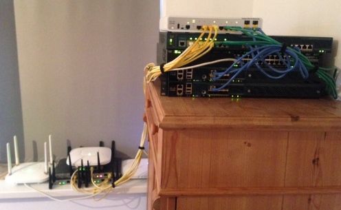
And because an picture says more than thousand words:

CCIE Wireless lab

The controllers
2x 5508
1x 2504
1x vWLC (not on the blueprint, but the technology is cool)

Access-points
1x 3702I (with the WSSI module, associated to my vWLC as “production” network)
1x 2602I (Associated to my “production” network as an WGB so I don’t have to hear the noise 🙂 )
1x 2602E (with some external antennas, also autonomous)
1x 3500I (Spectrum Expert / test AP for converged access)
5x 1242AG (All over the WLC’s…)

Switches
1x 3650-24PS (also for doing the converged access stuff, not on the 2.0 blueprint but it is coming anyway..)
1x 3560CG-12P
1x 3560-8PC

Phones
2x 7925G

For running WCS / Prime, MSE and ACS I have a VMware server collocated in a datacenter connected with a VPN on a ASA firewall. Some hardware I bought myself (the 3650 for example) and some borrowed from the company lab, which I’m grateful for.

I’m already looking forward to continue the lack of sleep for the next two months.. 😀

Cisco CleanAir Express

CleanAir

The CleanAir technology in Cisco’s access-point’s comes originally from the Cognio acquisition back in 2007. Cognio had a hardware chip that could do spectrum analysis and recognize non wifi interference. After this acquisition Cisco integrated this hardware capability right into its access-point’s. The first access-point with this technology was the 3500 and since then all the 2×00 and 3×00 access-points have CleanAir support.

An commonly misunderstanding is that the CleanAir makes an access-points change its channel when it discovers a (strong) non-wifi interference on the channel the access-point is currently on. RRM is the part of the WLC that is responsible for the power and channel configuration of your access-point, not CleanAir. CleanAir only detects. However, when you enable event driven RRM (EDRRM), the RRM algorithm will take the CleanAir information into account.

CleanAir Express

CleanAir Express was announced together with the 1600 access-point, but was not usable at the time due to the lack of software support. The only thing that Cisco published about this subject was that “it” was done in software on the access-point’s instead of doing it in hardware. Since than it is chaos around this subject because nobody really knows what to expect from CleanAir Express…

The documentation available today from Cisco on CleanAir Express does not help either. The primary reason for this (which I can think of) is that CleanAir Express has just been implemented since software 8.0, which is still fairly new and the marking people needed something to show earlier than the release of that code. A nice example is this document that states that “Air Qualty Index” is not supported with CleanAir Express, but from my own experience I can tell you that this just does work on 1600 and 1700 AP’s while running 8.0.110 code. See the example below.

(vWLC) >show ap inventory 1602E
NAME: “Cisco AP”    , DESCR: “Cisco Wireless Access Point”
PID: AIR-CAP1602E-E-K9,  VID: V01,  SN: FGL1734xxxxx

(vWLC) >show 802.11b cleanair air-quality 1602E
AQ = Air Quality

DFS = Dynamic Frequency Selection

Channel Avg AQ Min AQ Total Power (dBm) Total Duty Cycle (%) Interferer Power (dBm) Interferer Duty Cycle (%) Interferers DFS
——- —— —— —————– ——————– ———————- ————————- ———– —
1       98     98     -92               1                    -72                    2                         1


Conclusion

So what are the big differences between CleanAir and CleanAir Express? Well, from my experiences and from a functional standpoint there are no significant differences anymore since there is finally software which enables CleanAir Express. Because of it architecture CleanAir Express can only track up to three devices per radio (instead of 10) and it is somewhat a little slower, but for me that is now real deal breaker.

It is a pity that it took Cisco almost 2 years to enable it, but it is here and it does even more than the marketing people did told us upfront..  🙂

Sniffer mode on autonomous access-point

When using a WLC it is very easy to turn a access-point into a remote “sniffer” and let it send you captured data for a specify channel. A colleague of my asked if this was also possible for an autonomous access-point. I did not know a method to do this and also Google was not very helpful, so I decided to do some testing and did found a method to get the same results!

Autonomous access-points have a station-role called “scanner” which can be used in conjunction with the obsolete WLSE software. In this mode it sends raw captured data from the wireless spectrum to the WLSE for further analysis. Lucky for us Wireshark can also decode this packets. You have to configure your IPv4 address as destination and configure Wireshark to listen to this port and decode it as “CIWDS” (so not the PEEK type which has to be used with the WLC “sniffer” mode). From here one you can do whatever you want to do with the capture 😀

Int dot X
station-role scanner
monitor frames endpoint ip address 192.168.101.238 port 1337

Cisco WLC: Monitor total number of clients

For the majority of our customers I install Cisco Prime Infrastructure as “enhanced” monitoring tool for the wireless infrastructure. I say “enhanced” because the WLC itself does have a few monitoring features, but all of those are “real time” and not for historical purpose.

However, not all the customers need the features that Prime Infrastructure has to offer or they already have some “basic” network monitoring in place. In those cases it is sometimes handy to add the WLC in that monitoring, which is most of the times SNMP based.

There is always one question when it comes to SNMP; “what OID do I have to use to get information X?”. I wanted to monitor the total number of associated clients on a particular WLC, but found out that it is very hard to find the right OID for doing so. There is some Cisco documentation about SNMP monitoring on a WLC but thats more “advanced” monitoring.

It turned out to be OID .1.3.6.1.4.1.9.9.618.1.8.12.0 which returns the value as a “gauge”, if you also want to monitor the number of joined AP’s you can use OID .1.3.6.1.4.1.9.9.618.1.8.4.0. There you go! 🙂

QOS-4-QLIMIT_HQUEUE_VALUE_SYNC_ISSUE.. eh what?

Earlier this week I added a class to a already existing policy which was being used for outbound traffic-shaping. Nothing excited you would say? Well, not really. However.. it turned out that when I created the 15th class under the policy a worrying message appeared in the logging of the router:

%QOS-4-QLIMIT_HQUEUE_VALUE_SYNC_ISSUE

The policy did seem to work but this message was not giving me a warm feeling. So as a typical network engineer of the 21th century, I copied the message into Google in the hope to find out what the poor router was trying to tell me. Literately zero results, so that was very promising.

I knew that it had to be something with queues and the size of it (until the adding of this new class, everything was working fine). So I searched for some basic information about hold queues on ISR routers and how to configure them. I stumbled upon some interesting information, but still no satisfying answer on how to calculate which “hold queue size” was appropriated for my situation. So I reached out to TAC and the information they give me was very helpful, so I want to share it with the Internet 🙂

Once you configure class-based queuing on a ISR router, the default interface hold-queue is being changed to 1000 packets. Every class has a default queue-limit of 64, so once you are configuring the 15th class (which is the 16th if you count the default class, which is always there) you should have a hold-queue of 1024 packets (16*64). The hold-queue is 1000 packets so that is the reason why the message is being displayed. So what size should it be? As always it depends, but in consultation with with TAC I configured it to a size of 1984 packets without any problems and with some grow in mind. This was on a 2901 ISR with 50~70Mbit/s traffic placed as a Internet router (so just some basic routing, ACL’s and traffic-shaping). I hope this information can help you!